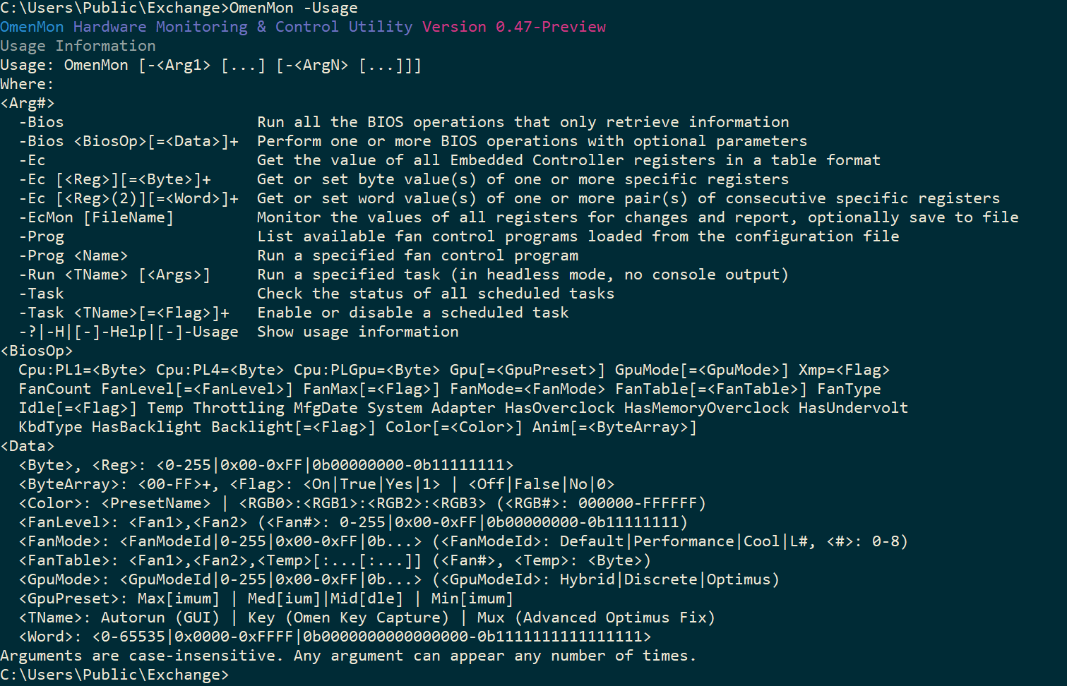
OmenMon Command-Line (CLI) Mode
- Operation Contexts / Operation Chain / Output Formatting
- BIOS Operations
- Embedded Controller Operations
- Fan Control Program Operations / Task Operations
- Data Input Formats / Error Messages
OmenMon runs in command-line mode if any command-line arguments are provided. Otherwise, it just launches the GUI.
Operation Contexts
Command-line operations are separated into contexts. A context is set by an argument that begins with a - (the minus sign).
Within a given context, a number of arguments can be provided, to be processed sequentially, until the context is changed with another argument starting with a -, or there are no more arguments to process.
The contexts are:
-BiosWMI BIOS operations: interacting with the firmware via HP-specific WMI routines-EcEmbedded Controller operations-EcMonEmbedded Controller monitor-ProgFan program operations-Task-RunTask operations-Usage--Usage-Help--Help-H-?Usage information
Context names are case-insensitive.
Operation Chain
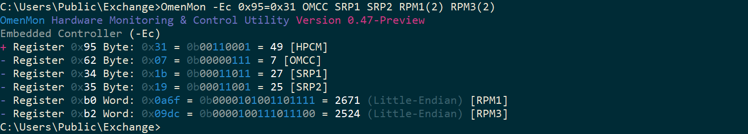
Multiple operations can be performed in a sequence. For example:
-Ec 0x95=0x31 OMCC SRP1 SRP2 RPM1(2) RPM3(2)
It is also possible while switching between different contexts, each of which can be called any number of times:
-Ec HPCM -Bios FanMode=Performance -Ec HPCM
If an incorrect context or argument is specified, the operation is interrupted to display usage information and any further arguments are ignored.
If an operation is executed that runs indefinitely, no further actions will be taken after that operation is terminated by the user. This presently applies to Embedded Controller monitoring with -EcMon and fan-control program execution with -Prog <Name>.
Output Formatting
- The first character in each row indicates the operation type:
-means a retrieval (get) operation+means an assignment (set) operation#means a list is being output, continuing the operation indicated in the last row that started with either a-or a+
- Binary values that start with
0bhave their high (set) bits highlighted in blue - Hexadecimal values that start with
0xare shown in a different (deemphasised) color if either none or all of the bits are high (set), i.e. when they equal0x00and0xFFrespectively - If only one bit is high (set), both binary and hexadecimal values are shown in red, i.e.
0x80=0b10000000 - Hexadecimal color values are an exception: red, green and blue are used show the respective color components instead
- Colors that appear on your system might differ depending on the console settings
BIOS Operations
-BiosRun all the BIOS operations that only retrieve information
-Bios <Op>[=<Data>]+Perform one or more BIOS operations with optional parameters

The available operations in the -Bios context are:
Cpu:PL1=<Byte> Cpu:PL4=<Byte> Cpu:PLGpu=<Byte> Gpu[=<GpuPreset>] GpuMode[=<GpuMode>] Xmp[=<Flag>]
FanCount FanLevel[=<FanLevel>] FanMax[=<Flag>] FanMode=<FanMode> FanTable[=<FanTable>] FanType
Idle[=<Flag>] Temp Throttling BornDate System Adapter HasOverclock HasMemoryOverclock HasUndervolt
KbdType HasBacklight Backlight[=<Flag>] Color[=<Color>] Anim[=<ByteArray>]
The operations, which are case-insensitive, are described below.
Adapter
-Bios AdapterRetrieve and interpret the smart power adapter status.
// Smart power adapter status
public enum AdapterStatus : byte {
    NotSupported     = 0x00,  // No smart power adapter support
    MeetsRequirement = 0x01,  // Sufficient power
    BelowRequirement = 0x02,  // Insufficient power
    BatteryPower     = 0x03,  // Not on AC power
    NotFunctioning   = 0x04,  // Malfunction
    Error            = 0xFF   // Error
}
Anim
-Bios AnimRetrieve the LED animation table-Bios Anim=<ByteArray>Set the LED animation table
The LED animation table is a 128-byte structure with an unknown format. On the OmenMon author’s laptop, it consists of zeroes entirely, and changes to it take no effect. However, the functionality to retrieve and set it is added for completeness so that it can be tested on other devices.
To set the LED animation table, use a string representation of a hexadecimal byte array as defined in the data input formats section.
This functionality can be expanded if more information regarding this feature emerges.
Backlight
-Bios BacklightRetrieve the keyboard backlight status-Bios Backlight=<Flag>Set the keyboard backlight status on or off
Backlight status is internally represented as the following byte value:
// Keyboard backlight toggle
public enum Backlight : byte {
    Off = 0x64,  // 0b01100100 - Keyboard backlight off
    On  = 0xE4   // 0b11100100 - Keyboard backlight on
}
BornDate
-Bios BornDateRetrieve the “Born-on Date” (BOD)
Color
-Bios ColorRetrieve the keyboard backlight color information-Bios Color=<Color>Set the keyboard backlight color
Where <Color> is either:
- Four colon-separated hexadecimal RGB color values
<RGB0>:<RGB1>:<RGB2>:<RGB3>- Where
<RGB#>is000000-FFFFFFeach - This is also the color preset specification format both in the configuration file and the GUI
- Where
- A configuration color preset
Hexadecimal color values appearing as output are highlighted in red, green and blue to indicate each respective color component.
Internally, the color table structure is defined in Hardware\BiosData.cs:
// RGB color value 24-bit data type
[StructLayout(LayoutKind.Sequential, Pack = 1)]
public struct RgbColor {
    public byte Red, Green, Blue;
}

// Keyboard backlight color zone
public enum KbdZone : byte {
    Right  = 0x00,  // Arrows, navigation block, right-hand modifier keys
    Middle = 0x01,  // Right-hand QWERTY block (F6-F12), delimited by the keys T, G, and B
    Left   = 0x02,  // Left-hand QWERTY block (F1-F5), delimited by the keys R, F, and V
    Wasd   = 0x03   // The keys W, A, S, and D
}

// Padding of the color table
// Constant but defined here since it appears several times
public const int COLOR_TABLE_PAD = 24;

// Keyboard backlight color table data type
// Consistent with how the data is stored by the BIOS
[StructLayout(LayoutKind.Sequential, Pack = 1, Size = 128)]
public struct ColorTable {
    public byte ZoneCount; // Number of color zones

    [MarshalAs(UnmanagedType.ByValArray, SizeConst = COLOR_TABLE_PAD, ArraySubType = UnmanagedType.U1)]
    byte[] Padding; // Has to be this way instead of LayoutKind.Explicit, alignment exception otherwise

    // See KbdZone (enum)
    [MarshalAs(UnmanagedType.ByValArray, SizeConst = 4)] // SizeConst has to be defined at compilation time
    public RgbColor[] Zone;

}
The above snippet has been edited for brevity. See the source for the entire definition.
Although some abstraction capability is implemented, only four-zone backlight keyboards are currently supported, as that is what the author’s hardware supports.
Cpu:PL1
-Bios Cpu:PL1=<Byte>Set the CPU Power Limit 1 to the specified threshold in Watts [W]
The current value of this setting cannot be queried.
Cpu:PL4
-Bios Cpu:PL4=<Byte>Set the CPU Power Limit 4 to the specified threshold in Watts [W]
The current value of this setting cannot be queried. The default value is output as byte #5 of the System data.
Cpu:PLGpu
-Bios Cpu:PLGpu=<Byte>Set the CPU Power Limit concurrent with GPU to the specified threshold in Watts [W]
The current value of this setting is output as byte #8 of the System data.
Note: This setting is likely applicable only from Cybug 23C1 (2023 Omen 17) onwards.
FanCount
-Bios FanCountRetrieve the number of fans
For obvious reasons, this is a read-only value.
FanLevel
-Bios FanLevelRetrieve the current speed level for each fan-Bios FanLevel=<Fan1>,<Fan2>Set the fan speed levels to the given comma-separated values
Where each <Fan#> is a byte-sized speed level specified in a decimal 0-255, hexadecimal 0x00-0xFF or even binary 0b00000000-0b11111111 format stated in thousands of revolutions per minute [krpm].
FanMax
-Bios FanMaxCheck if the fan is currently operating in maximum-speed mode-Bios FanMax=<Flag>Toggle maximum fan speed mode on or off
FanMode
-Bios FanMode=<FanMode>Set the fan performance mode to the given value
Fan mode can be set to any byte-sized numerical value specified as a decimal, hexadecimal or binary string representation but it’s more practical to use an enumerated constant:
// Fan performance mode
// Source: HP.Omen.Core.Common.PowerControl.PerformanceMode
public enum FanMode : byte {
    LegacyDefault     =  0,  // 0x00 = 0b00000000
    LegacyPerformance =  1,  // 0x01 = 0b00000001
    LegacyCool        =  2,  // 0x02 = 0b00000010
    LegacyQuiet       =  3,  // 0x03 = 0b00000011
    LegacyExtreme     =  4,  // 0x04 = 0b00000100
    L8                =  4,  // 0x04 = 0b00000100
    L0                = 16,  // 0x10 = 0b00010000
    L5                = 17,  // 0x11 = 0b00010001
    L1                = 32,  // 0x20 = 0b00100000
    L6                = 33,  // 0x21 = 0b00100001
    Default           = 48,  // 0x30 = 0b00110000
    L2                = 48,  // 0x30 = 0b00110000
    Performance       = 49,  // 0x31 = 0b00110001
    L7                = 49,  // 0x31 = 0b00110001
    L3                = 64,  // 0x40 = 0b01000000
    Cool              = 80,  // 0x50 = 0b01010000
    L4                = 80   // 0x50 = 0b01010000
}
On all recent systems with Thermal Policy Version 1, the three modes in use are Default, Performance and Cool. The use of the other values appears to be limited to older systems with Thermal Policy Version 0. Note all these identifiers are case-sensitive.
This value cannot be queried via the BIOS, however it can be retrieved from the Embedded Controller register HPCM = 0x95.
FanTable
-Bios FanTableRetrieve and interpret the fan speed-level table-Bios FanTable=<FanTable>Rewrite the fan speed-level table with the given values
The fan table is a 128-byte structure with a specific format. On the OmenMon author’s laptop, it contains some defaults that however seem to never apply. For experimentation, the preset is reproduced in the example configuration file under the name “OEM Test”.
Changes to the table seem to take no effect. However, the functionality to retrieve and set it is added for completeness so that it can be tested on other devices. The entries can be specified as colon-separated per-level definitions with three comma-separated byte-sized values: <Fan1>,<Fan2>,<Temp>[:...[:...]] where:
<Fan#>is the level of a given fan as used with FanLevel, i.e. a value in thousands of revolutions per minute [krpm]<Temp>is a temperature threshold value
Internally, the fan table structure is defined in Hardware\BiosData.cs:
// Fan 1 & 2 speed level for a given temperature readout data type
[StructLayout(LayoutKind.Sequential, Pack = 1)]
public struct FanLevel {
    public byte Fan1Level, Fan2Level, Temperature;
}

// Fan speed level table data type
// Consistent with how the data is stored by the BIOS
[StructLayout(LayoutKind.Sequential, Pack = 1, Size = 128)]
public struct FanTable {
    public byte FanCount; // Number of fans (2)
    public byte LevelCount; // Number of level entries (14)

    // Fan speed level entry array
    [MarshalAs(UnmanagedType.ByValArray, SizeConst = 14)] // SizeConst has to be defined at compilation time
    public FanLevel[] Level;

}
The above snippet has been edited for brevity. See the source for the entire definition. Currently, the number of fan level entries is capped at 14 due to an implementation constraint.
This functionality can be expanded in the future if more information regarding this feature emerges. It is the author’s understanding that it might only be applicable to certain HP Omen desktop systems.
FanType
-Bios FanTypeRetrieve and interpret the fan type register
On a two-fan system, each nibble (four highest or four lowest bits) of the returned value define the fan type as follows:
// Fan type (per nibble)
public enum FanType : byte {
    Unsupported = 0x00,  // No fan support
    Cpu         = 0x01,  // Is a CPU fan
    Gpu         = 0x02,  // Is a GPU fan
    Exhaust     = 0x03,  // Is an exhaust fan
    Pump        = 0x04,  // Is a pump fan
    Intake      = 0x05   // Is an intake fan
}
Gpu
-Bios GpuRetrieve and interpret the current GPU power settings-Bios Gpu=<GpuPreset>Set the GPU power preset
Internally, the data is represented as follows:
// Custom Total Graphics Power (TGP) limit switch
public enum GpuCustomTgp : byte {
    Off = 0x00,  // Base TGP only
    On  = 0x01   // Custom TGP enabled
}

// GPU device power state list
public enum GpuDState : byte {
    D1 = 0x01,  // Device power state 1
    D2 = 0x02,  // Device power state 2
    D3 = 0x03,  // Device power state 3
    D4 = 0x04,  // Device power state 4
    D5 = 0x05   // Device power state 5
}

// Processing Power AI Boost (PPAB) switch
public enum GpuPpab : byte {
    Off = 0x00,  // Boost disabled
    On  = 0x01   // Boost enabled
}

// Graphics power settings data structure
// Consistent with how the data is stored by the BIOS
[StructLayout(LayoutKind.Sequential, Pack = 1, Size = 4)]
public struct GpuPowerData {
    public GpuCustomTgp CustomTgp;  // Custom Total Graphics Power (TGP) limit
    public GpuPpab Ppab;            // Processing Power AI Boost (PPAB)
    public GpuDState DState;        // GPU device power state
    public byte PeakTemperature;    // Sensor threshold, observed: 75°C (0x4B), 87°C (0x57)
}
For convenience in changing these settings, they are grouped under three presets:
Min[imum]disables both custom TGP and PPAB leaving base TGP only, i.e.GpuCustomTgp == OffandGpuPpab == OffMax[imum]enables both custom TGP and PPAB, i.e.GpuCustomTgp == OnandGpuPpab == OnMed[ium]orMid[dle]enables the former but disables the latter- When specified from the command line, these preset names are case-insensitive
- Peak-temperature threshold is set to
0, i.e. disabled
// GPU Power Settings
public enum GpuPowerLevel : byte {
    Minimum = 0x00,  // Base TGP only
    Medium  = 0x01,  // Custom TGP
    Maximum = 0x02   // Custom TGP & PPAB
}
If changes to these settings do not seem to take effect on first try, particularly when downgrading performance, i.e. switching from Maximum to Medium or Minimum, you might want to try adjusting the GpuPowerSetInterval configuration setting.
GpuMode
-Bios GpuModeRetrieve and interpret the current GPU mode-Bios GpuMode=<GpuMode>Switch the GPU mode (a reboot is required)
// Graphics mode (predates Advanced Optimus)
// Source: HP.Omen.Core.Model.DataStructure.Modules.GraphicsSwitcher
public enum GpuMode : byte {
    Hybrid   = 0x00,  // Hybrid graphics mode
    Discrete = 0x01,  // Discrete GPU exclusive mode
    Optimus  = 0x02   // nVidia Optimus mode
}
This is not Advanced Optimus but the equivalent of the setting available in the UEFI (BIOS) Setup. A reboot is required for it to take effect. However, being able to toggle the setting programmatically still saves the hassle of having to open the Setup menu every time.
On models that do not support GPU mode switching, the call to retrieve GPU mode will silently fail and return Hybrid. For GPU mode switching capability check, see byte #7 of the System data. Manual GPU mode setting is still allowed on systems that do not support it but is likely to return an error.
On the author’s 8A14 model, where the Supported8 flag is set, this seems to toggle between Discrete and Optimus. The value for Hybrid is never used. On slightly older systems such as the 88F7, where the Supported4 flag is sset, it is the Optimus mode that is not used, and trying to switch it on causes an error.
For the record, Advanced Optimus settings can only be changed from within nVidia Control Panel (or via one of the nVidia Display Container notification-area icons, if you enabled it).
HasBacklight
-Bios HasBacklightCheck if keyboard backlight is supported
If unsupported, the call will silently fail and return a zero status.
HasMemoryOverclock
-Bios HasMemoryOverclockCheck if memory overclocking is supported
If unsupported, the call will silently fail and return a zero status.
HasOverclock
-Bios HasOverclockCheck if overclocking is supported
If unsupported, the call will silently fail and return a zero status.
HasUndervolt
-Bios HasUndervoltCheck if undervolting is supported
If unsupported, the call will silently fail and return a zero status.
Idle
-Bios Idle=<Flag>Toggle idle mode on or off
// Idle mode status
public enum Idle : byte {
    Off = 0x00,  // Disabled
    On  = 0x01   // Enabled
}
This is toggled by the Omen Hub (Omen Control Center) if no user activity is detected, which in turn influences the power management settings. By comparison, OmenMon does not monitor the user activity or attempt to change this behind your back.
KbdType
-Bios KbdTypeRetrieve and interpret the keyboard type
// Keyboard type
public enum KbdType : byte {
    Standard   = 0x00,  // Standard layout
    WithNumPad = 0x01,  // Standard layout with numerical block
    TenKeyLess = 0x02,  // Extra navigation keys but no numerical block
    PerKeyRgb  = 0x03   // Independently-definiable color for each key (?)
}
The layout of the TenKeyLess keyboard is as follows:
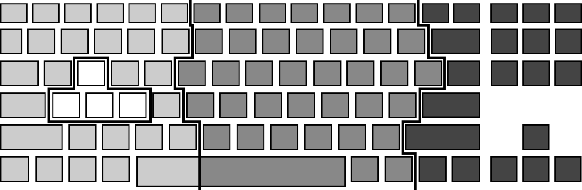
The functionality of this application has only been tested with this specific keyboard layout.
System
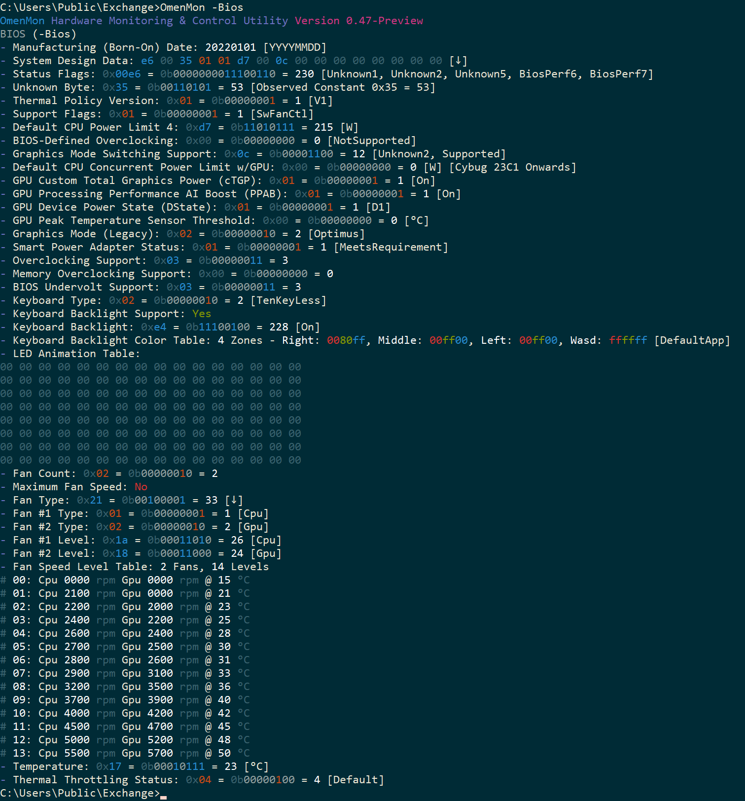
-Bios SystemRetrieve and interpret the system design data
The output from this command should be self-explanatory, however not all of the values are currently documented. Here’s how the output is processed internally:
// Thermal policy version
public enum ThermalPolicyVersion : byte {
    V0 = 0x00,  // Legacy devices
    V1 = 0x01,  // Current devices
}

// BIOS-defined overclocking support
// Observed: 0x00
public enum SysBiosOc : byte {
    NotSupported = 0x00,  // No
    Supported    = 0x01   // Yes
}

// Graphics switching support
// Observed: 0x06 = 0b00000110 [88F7], 0x0C = 0b00001100 [8A14]
[Flags]
public enum SysGpuModeSwitch : byte {
    Unset0     = 0x01,  // Bit #0: Observed 0: Unset
    Unset1     = 0x02,  // Bit #1: Observed 0: Unset
    Supported4 = 0x04,  // Bit #2: Observed 1: Set - Also Supported (?)
    Supported8 = 0x08,  // Bit #3: Observed 1: Set - Supported
    Unset4     = 0x10,  // Bit #4: Observed 0: Unset
    Unset5     = 0x20,  // Bit #5: Observed 0: Unset
    Unset6     = 0x40,  // Bit #6: Observed 0: Unset
    Unset7     = 0x80   // Bit #7: Observed 0: Unset
}

// System support flags
// Observed: 0x01
[Flags]
public enum SysSupportFlags : byte {
    SwFanCtl          = 0x01,  // Bit #0: Software fan control supported
    ExtremeMode       = 0x02,  // Bit #1: Extreme Mode supported
    ExtremeModeUnlock = 0x04   // Bit #2: Extreme Mode unlocked
}

// System status flags
// Observed: 0x00E6 = 0b0000000011100110
//        >= 0x0118 = 0b0000000100011000 - PPAB check
//        >= 0x00C8 = 0b0000000011001000 - BIOS Performance Mode check
[Flags]
public enum SysStatusFlags : ushort {
    Unset0        = 0x0001,  // Bit #0: Observed 0: Unset
    Unknown1      = 0x0002,  // Bit #1: Observed 1: Set
    Unknown2      = 0x0004,  // Bit #2: Observed 1: Set
    BiosPerfPpab3 = 0x0008,  // Bit #3: BIOS Performance Mode or PPAB check common flag (Observed 0: Unset)
    Ppab4         = 0x0010,  // Bit #4: PPAB check flag #2 of 3 (Observed 0: Unset)
    Unknown5      = 0x0020,  // Bit #5: Observed 1: Set
    BiosPerf6     = 0x0040,  // Bit #6: BIOS Performance Mode check flag #2 of 3 (Observed 1: Set)
    BiosPerf7     = 0x0080,  // Bit #7: BIOS Performance Mode check flag #3 of 3 (Observed 1: Set)
    Ppab8         = 0x0100,  // Bit #8: PPAB check flag #3 of 3 (Observed 0: Unset)
    Unset9        = 0x0200,  // Bit #9: Observed 0: Unset
    UnsetA        = 0x0400,  // Bit #A: Observed 0: Unset
    UnsetB        = 0x0800,  // Bit #B: Observed 0: Unset
    UnsetC        = 0x1000,  // Bit #C: Observed 0: Unset
    UnsetD        = 0x2000,  // Bit #D: Observed 0: Unset
    UnsetE        = 0x4000,  // Bit #E: Observed 0: Unset
    UnsetF        = 0x8000   // Bit #F: Observed 0: Unset
}

// System design data structure
// Consistent with how the data is stored by the BIOS
// Observed: E6 00 35 01 01 D7 00 0C 00 ..
[StructLayout(LayoutKind.Sequential, Pack = 1, Size = 128)]
public struct SystemData {

    // Bytes #0 & #1: Status flags
    public SysStatusFlags StatusFlags;

    // Byte #2: Unknown
    // Observed: 0x35
    public byte Unknown2;

    // Byte #3: Thermal policy version
    public ThermalPolicyVersion ThermalPolicy;

    // Byte #4: Support flags
    public SysSupportFlags SupportFlags;

    // Byte #5: CPU Power Limit 4 default value
    // Observed: 0xD7 == 215 [W]
    public byte DefaultCpuPowerLimit4;

    // Byte #6: BIOS-defined overclocking support
    public SysBiosOc BiosOc;

    // Byte #7: Graphics switching support
    public SysGpuModeSwitch GpuModeSwitch;

    // Byte #8: CPU Concurrent Power Limit with GPU default value
    // Observed: 0x00, apparently applicable from Cybug 23C1 (2023 Omen 17) onwards
    public byte DefaultCpuPowerLimitWithGpu;

    // Unknown block observed empty as of now
    [MarshalAs(UnmanagedType.ByValArray, SizeConst = 119)]
    public byte[] RawBlock;

    // Initializes the system design data structure from a data array
    public SystemData(byte[] data) {
        StatusFlags = (SysStatusFlags) (ushort) (data[1] << 8 | data[0]);
        Unknown2 = data[2];
        ThermalPolicy = (ThermalPolicyVersion) data[3];
        SupportFlags = (SysSupportFlags) data[4];
        DefaultCpuPowerLimit4 = data[5];
        BiosOc = (SysBiosOc) data[6];
        GpuModeSwitch = (SysGpuModeSwitch) data[7];
        DefaultCpuPowerLimitWithGpu = data[8];
        RawBlock = new byte[119];

        // Copy over the rest of the array, in case
        // it ends up being populated too in future versions
        Array.Copy(data, 9, RawBlock, 0, data.Length < 128 ? data.Length - 9 : 119);
    }

}
Temp
-Bios TempRetrieve the temperature sensor reading
Note: Bear in mind the observed temperature readings from this sensor seem to consistently be much lower than from any of the Embedded Controller sensors.
Throttling
-Bios ThrottlingCheck the system thermal throttling status
// Throttling
public enum Throttling : byte {
    Unknown = 0x00,  // Unknown state (BIOS call failed)
    On      = 0x01,  // Thermal throttling enabled
    Default = 0x04   // Observed default state
}
Note: On 2023 models, this seems to return BIOS error code 6. In such scenarios (i.e. when the BIOS call fails), the status will be reported as 0x00 Unknown.
Xmp
-Bios Xmp=<Flag>Toggle between the default memory profile and XMP
This setting does not seem to be supported on the author’s hardware platform.
Embedded Controller Operations
The following operations are available:
-EcGet all register values in a table format

-Ec <Reg>Get the byte value of a given register-Ec <Reg>(2)Get the word value of two consecutive registers (little-endian)-Ec <Reg>=<Byte>Set a given register to a given byte value-Ec <Reg>(2)=<Word>Set the two consecutive registers to a given word value (little-endian)
While the application is intended specifically for the HP Omen platform, Embedded Controller operations should run on any hardware equipped with an Embedded Controller, such as laptops, mini PCs, and other non-desktop computers.
However, keep in mind the register identifiers are platform-specific and will have no significance whenever the underlying hardware differs from the HP Omen 8A14 platform these are based on.
Embedded Controller Register Identifiers
Aliases can be used to reference the Embedded Controller registers. These mostly originate from the ACPI DSDT table but with some extensions, as defined in Hardware\EcData.cs:
#region Embedded Controller Register Information
        // Embedded Controller register identifiers
        // Labels based on ACPI DSDT for HP 08A14 (Ralph 21C2) except:
        // SMxx - Single 32-bit register starting with SMD0 (until SMEF)
        // BFCD, BADD, MCUS, MBRN, MBCW - Second byte for word-sized registers BFCC, BADC, MCUR, MBRM, MBCV
        // BXXX, GSXX, SHXX, SXXX - Composite register where all identifiers start with the same letter
        // RXnc - Composite registers with varying identifiers, where <n> - # of bits, <c> - sequential count
        // Xxxx - Registers with no DSDT label where purpose identified, and <xxx> is a descriptive string

        public enum Register : byte {

            // Identified
            XSS1 = 0x2C,  // L Fan Set Speed [%]
            XSS2 = 0x2D,  // R Fan Set Speed [%]
            XGS1 = 0x2E,  // L Fan Get Speed [%]
            XGS2 = 0x2F,  // R Fan Get Speed [%]
            SRP1 = 0x34,  // L Fan Set Speed [krpm]
            SRP2 = 0x35,  // R Fan Set Speed [krpm]
            TNT2 = 0x47,  // Temperature [°C]
            TNT3 = 0x48,  // Temperature [°C]
            TNT4 = 0x49,  // Temperature [°C]
            IRSN = 0x4A,  // Temperature [°C]
            TNT5 = 0x4B,  // Temperature [°C]
            CPUT = 0x57,  // Temperature: CPU [°C]
            RTMP = 0x58,  // Temperature [°C]
            TMP1 = 0x59,  // Temperature [°C]
            XHID = 0x5F,  // HID Disable Toggle
            OMCC = 0x62,  // Manual Fan Control
            XFCD = 0x63,  // Manual Fan Auto Countdown [s]
            HPCM = 0x95,  // Performance Mode
            XBCH = 0x96,  // Battery Charge Level
            QBHK = 0xA0,  // Last Hotkey
            QBBB = 0xA2,  // HID-Related (?)
            RPM1 = 0xB0,  // L Fan Get Speed [rpm] 1/2
            RPM2 = 0xB1,  // L Fan Get Speed [rpm] 2/2
            RPM3 = 0xB2,  // R Fan Get Speed [rpm] 1/2
            RPM4 = 0xB3,  // R Fan Get Speed [rpm] 2/2
            GPTM = 0xB7,  // Temperature: GPU [°C]
            CLOW = 0xBA,  // Minimum Power State
            CMAX = 0xBB,  // Maximum Power State
            FFFF = 0xEC,  // Max Fan Speed Toggle
            SFAN = 0xF4,  // Fan Toggle
            FTHM = 0xF9,  // Bit #4: GFXM, #7: FTHM Thermal Threshold Reached

            // Unidentified but mentioned in DSDT
            SMPR = 0x00,
            SMST = 0x01,
            SMAD = 0x02,
            SMCM = 0x03,
            SMD0 = 0x04,  // SMD0 01/32
            SMD1 = 0x04,  // SMD0 02/32
            SMD2 = 0x05,  // SMD0 03/32
            SMD3 = 0x06,  // SMD0 04/32
            SMD4 = 0x07,  // SMD0 05/32
            SMD5 = 0x08,  // SMD0 06/32
            SMD6 = 0x09,  // SMD0 07/32
            SMD7 = 0x0A,  // SMD0 08/32
            SMD8 = 0x0B,  // SMD0 09/32
            SMD9 = 0x0C,  // SMD0 10/32
            SMDA = 0x0D,  // SMD0 11/32
            SMDB = 0x0E,  // SMD0 12/32
            SMDC = 0x0F,  // SMD0 13/32
            SMDD = 0x10,  // SMD0 14/32
            SMDE = 0x11,  // SMD0 15/32
            SMDF = 0x12,  // SMD0 16/32
            SME0 = 0x13,  // SMD0 17/32
            SME1 = 0x14,  // SMD0 18/32
            SME2 = 0x15,  // SMD0 19/32
            SME3 = 0x16,  // SMD0 20/32
            SME4 = 0x17,  // SMD0 21/32
            SME5 = 0x18,  // SMD0 22/32
            SME6 = 0x19,  // SMD0 23/32
            SME7 = 0x1A,  // SMD0 24/32
            SME8 = 0x1B,  // SMD0 25/32
            SME9 = 0x1C,  // SMD0 26/32
            SMEA = 0x1E,  // SMD0 27/32
            SMEB = 0x1F,  // SMD0 28/32
            SMEC = 0x20,  // SMD0 29/32
            SMED = 0x21,  // SMD0 30/32
            SMEE = 0x22,  // SMD0 31/32
            SMEF = 0x23,  // SMD0 32/32
            BCNT = 0x24,
            SMAA = 0x25,
            BTPL = 0x30,  // Word together with BTPL
            BTPH = 0x31,  // Word together with BTPH
            BCLC = 0x32,
            ECL1 = 0x37,
            ECL2 = 0x38,
            ECL4 = 0x39,
            EL1R = 0x3A,
            EL2R = 0x3B,
            EL4R = 0x3C,
            RX3A = 0x40,  // Bit #0: SW2S, #3: ACCC, #4: TRPM
            RX4A = 0x41,  // Bit #0: W7OS, #1: QWOS, #3: SUSE, #4: RFLG
            RX2A = 0x42,  // Bit #1: CALS, #4: KBBL
            RX3B = 0x43,  // Bit #2: ACPS, #3: ACKY, #4: GFXT
            DSMB = 0x44,
            STRM = 0x4C,
            LIDE = 0x4E,
            RX4B = 0x50,  // Bit #2: PTHM, #4: S3CA, #5: DPTL, #6: IHEF
            ECLS = 0x52,
            CPHK = 0x53,
            EC45 = 0x55,
            HPTC = 0x5B,
            SHPM = 0x61,
            RX3C = 0x67,  // Bit #0: LDBG, #2: GC6R, #3: IGC6
            PLGS = 0x68,
            BXXX = 0x69,  // Bit #4: BCTF, #5: BMNF, #6: BTVD, #7: BF10
            GWKR = 0x6C,
            BADC = 0x70,  // Word together with BADD
            BADD = 0x71,  // Word together with BADC
            BFCC = 0x72,  // Word together with BFCD
            BFCD = 0x72,  // Word together with BFCC
            BVLB = 0x74,
            BVHB = 0x75,
            BDVO = 0x76,
            ECTB = 0x7F,
            MBST = 0x82,
            MCUR = 0x83,  // Word together with MCUS
            MCUS = 0x84,  // Word together with MCUR
            MBRM = 0x85,  // Word together with MBRN
            MBRN = 0x86,  // Word together with MBRM
            MBCV = 0x87,  // Word together with MBCW
            MBCW = 0x88,  // Word together with MBCV
            GPUT = 0x89,
            LEDM = 0x8B,
            MBFC = 0x8D,
            NVDO = 0x90,
            ECDO = 0x91,
            GSXX = 0x94,  // Bit #0: GSSU, #1: GSMS
            ADPX = 0xA3,
            RX2B = 0xA4,  // Bit #0: MBTS, #7: BACR
            MBDC = 0xA5,
            RX2C = 0xA7,  // Bit #0: ENWD, #1: TMPR
            SXXX = 0xAA,  // Bit #1: SMSZ, #2: SE1N, #3: SE2N, #4: SOIE, #7 RCDS
            SADP = 0xAD,
            EPWM = 0xB8,
            DPPC = 0xC1,
            SHXX = 0xC5,  // Bit #0: SHB1, #1: SHB2, #2: SHB3, #3: SHB4, #4: SHOK, #5: SHFL, #6: SHNP, #7: SHEN
            CVTS = 0xC6,
            CSFG = 0xCA,
            EBPL = 0xD0,
            S1A1 = 0xD2,
            S2A1 = 0xD3,
            PSHD = 0xD4,
            PSLD = 0xD5,
            DBPL = 0xD6,
            STSP = 0xD7,
            PSIN = 0xDA,
            RX4C = 0xDB,  // Bit #0: PSKB0, #1: PSTP, #3: PWOL, #4: RTCE
            S1A0 = 0xDC,
            S2A0 = 0xDD,
            NVDX = 0xDE,
            ECDX = 0xDF,
            DLYT = 0xE0,
            DLY2 = 0xE1,
            KBT0 = 0xE2,
            SFHK = 0xE6,
            DTMT = 0xE9,
            PL12 = 0xEA,
            ETMT = 0xEB,
            RX2D = 0xF0,  // Bit #0: PARS, #7: MUCR
            RX2E = 0xF2,  // Bit #0: ZPDD, #7: ENPA
            HDMI = 0xF7,
            NVDS = 0xF8
        }
#endregion
Embedded Controller Monitor
-EcMon [FileName]Monitor the Embedded Controller registers for changes over time, optionally saving to a file on exit
The monitor will keep running indefinitely. To terminate it, press Ctrl-C.
To control how often the readings are updated, use the EcMonInterval configuration setting.
Saving Data to a File
If [FileName] is specified, upon termination the data will be saved to a text file in the current directory
- An existing file will be silently overwritten
- If the file cannot be accessed, no data will be saved
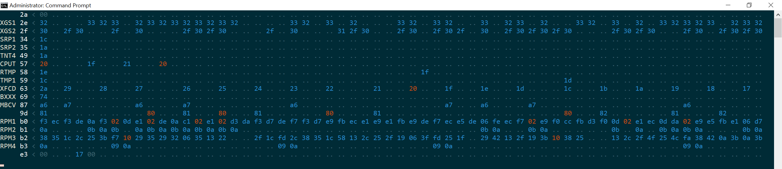
The format of the file is as follows:
#\Reg  13 2c 2d 31
00000  2a 01 01 ce
00001  2a 00 00 00
00002  2b 01 00 00
00003  2c 00 00 ce
00004  2c 01 01 ce
00005  2c 00 00 00
Where:
- The file starts with
#\Regas a hint to the meaning of the colums and rows - Each column is an Embedded Controller register (here, these are
0x13,0x2c,0x2dand0x31) - Each row is the register value at the given point in time, specifically:
nnnnn× EcMonInterval milliseconds [ms] since the monitoring started
In other words, the text-file output is transposed from the screen output, where the registers appear vertically.
Fan Control Program Operations
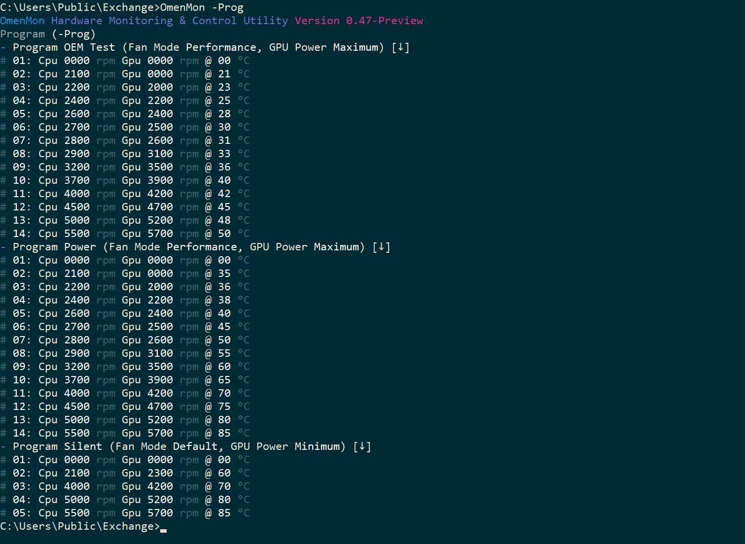
-ProgList available fan control programs loaded from the configuration file-Prog <Name>Run a specified fan control program
The program will keep running indefinitely. To terminate it, press Ctrl-C.
For more details regarding this functionality, see Fan Programs.
Task Operations
-Run <TName> [<Args>]Run a specified task (in headless mode, no console output)-TaskCheck the status of all scheduled tasks-Task <TName>[=<Flag>]+Enable or disable a scheduled task

The available tasks are as follows:
Guiwill start the application automatically whenever a user logs inKeywill trigger whenever the Omen key is pressed to launch the application and perform an action in accordance with the KeyCustomAction and KeyToggleFanProgram configuration settingsMuxwill trigger whenever the nVidia Advanced Optimus switches the GPU, and if the discrete GPU is being enabled the first time following a reboot, it will:- Reapply the color profile – to workaround the bug where the color profile is not being applied
- Restart the Windows Explorer shell – to workaround the bug where the screen stutters
- Restart the nVidia Display Container service – to restore any nVidia notification-area icons, which no longer appear following the Explorer shell restart
More tasks may be added in the future if need be. Meanwhile, the specifics of each task are hard-coded into the application, with parameters defined internally in Library\ConfigData.cs:
// Scheduled task data
public static Dictionary<TaskId, string[]> Task =
    new Dictionary<TaskId, string[]>() {
        [TaskId.Gui] = new string[] { AppName, "-Run Gui" },
        [TaskId.Key] = new string[] { AppName + " Key", "-Run Key", "root\\wmi", "SELECT * FROM hpqBEvnt WHERE eventData = 8613 AND eventId = 29" },
        [TaskId.Mux] = new string[] { AppName + " Mux", "-Run Mux", "root\\default", "SELECT * FROM RegistryValueChangeEvent WHERE Hive = \"" + RegHiveMachine + "\" AND KeyPath = \"" + RegMuxKey + "\" AND ValueName = \"" + RegMuxValue + "\"" }
};
As outlined above, the Key event depends on the Omen key event being reported by the hardware via the WMI so that the following query returns a result: SELECT * FROM hpqBEvnt WHERE eventData = 8613 AND eventId = 29. The Gui task will run regardless but the application itself will not start in GUI mode on non-compatible hardware. Thus, both the Gui and Key tasks are applicable to HP Omen hardware only.
By contrast, the Mux task should in principle work with any nVidia Advanced Optimus hardware as it does not depend on any functionality specific to HP Omen.
Data Input Formats
<Byte>is a hexadecimal0x<00-FF>, decimal<0-255>or binary0b<00000000-11111111>value- And so is
<Reg>except DSDT-based register names can be used as well, listed inHardware\EcData.cs
- And so is
<ByteArray>is a string of one or more hexadecimal values<00-FF><Flag>is a Boolean value: eitherOn,True,Yes,1orOff,False,No,0(case-insensitive)<Word>is a hexadecimal0x<0000-FFFF>, decimal<0-65535>or binary0b<0000000000000000-1111111111111111>value
Other <Data> are context-dependent parameters to an operation:
<Color>are four hexadecimal RGB color values<RGB0>:<RGB1>:<RGB2>:<RGB3>where<RGB#>is000000-FFFFFFeach<FanLevel>are fan speed levels for each fan respectively, separated by a comma<Fan1>,<Fan2>where<Fan#>, the speed level for each fan, can theoretically be any value between0-255or0x00-0xFFbut the valid settings appear to be up to around55at most, indicating 5,500 rpm, for the CPU fan, or57for the GPU fan.<FanMode>:<FanModeId|0-255|0x00-0xFF|0b...>(<FanModeId>:Default|Performance|Cool|L#,<#>:0-8)- Fan mode can be set to any numerical value but it’s more practical to use an enumerated constant. On all recent systems with Thermal Policy Version 1, the three modes in use are
Default,PerformanceandCool. Note these are case-sensitive.
- Fan mode can be set to any numerical value but it’s more practical to use an enumerated constant. On all recent systems with Thermal Policy Version 1, the three modes in use are
<FanTable>:<Fan1>,<Fan2>,<Temp>[:...[:...]](<Fan#>,<Temp>:<Byte>)<GpuMode>:<GpuModeId|0-255|0x00-0xFF|0b...>(<GpuModeId>:Hybrid|Discrete|Optimus)- Similarly to the fan mode, the enumerated constants
Hybrid,DiscreteandOptimusare also case-sensitive. On newer systems, the choice is between the two latter. This is equivalent to the BIOS settings, and requires a reboot; it’s not the Advanced Optimus switch.
- Similarly to the fan mode, the enumerated constants
<GpuPreset>:Max[imum]|<Med[ium]|Mid[dle]>|Min[imum]- Here,
Minimumis Base TGP only.Mediumis Custom TGP.Maximumis both Custom TGP and PPAB. These values are case-insensitive.
- Here,
<TName>:Guifor automatic startup on logon |Keyfor Omen key capture |Muxfor Advanced Optimus fix
Error Messages
In command-line mode, error messages are output to the console instead of triggering a message-box window:
